"Chris Shute's Matchbox Manipulator" by Dusty - 08/04/2011
360.219 bytes - 2.129 parts
Description
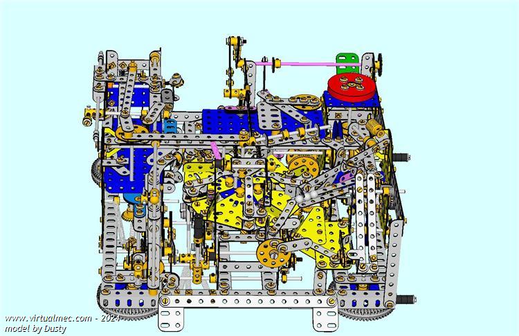
CHRIS SHUTE’S MATCHBOX MANIPULATOR
This is the VirtualMec representation of the Matchbox Manipulator designed by Chris Shute and which was first described in Issue 54 of CQ Magazine. The frame remains the same and the carousel is substantially the same apart from being mounted on a ten hole 2½” faceplate instead of the two 1” bushwheels described in the article. The rest of the model has been substantially modified since publication.
The model is completely mechanical and will fill up to five matchboxes each with a single ball bearing then empty them again before continuously repeating the cycle all over again.
A video of the working model can be seen at (http://www.youtube.com/watch?v=QuzM3TCBhek )
The model uses some parts not available in VirtualMec and look-alike parts (coloured in pink in the VirtualMec model) have been used as substitutes.
When referring to the parts list from the loaded mdl file you should change the pink coloured look-alike parts for the following substitutes:
Delete 3 tension springs (part 43), 2 Angle brackets, 10 nuts and 10 bolts and replace with 3 narrow springs hooked at each end (hooks attach to frame at Angle mounting points and on rods).
Delete 1 collar and 1 one inch screwed rod and replace with a shock absorber pin (part 120e) –part of the on/off switch at the rear of the model. Delete the other adjacent 1” screwed rod and replace it with a piece of spring cord attached to part 120e at one end and wound round the bolt holding the ¾ washer at the other end.
Delete the 8 x 1½” strips and replace with 1 narrow spacer strip (part 260c).
Delete the remaining 1 x 1½” strip and replace with a scrap 3 hole piece of plastic plate
Delete the 5 x 1” screwed rods and the 5 aero collars (part 59a) by which they are attached (on the carousel) and replace with lengths of spring cord
Delete 1 x 5” axle rod and 1 x 2” axle rod and replace with a 7” axle rod (the single axle rod coloured pink in the model is in fact two rods joined in the cam (part 131)).
Delete the Junior Power Drive Motor and replace with a more powerful substitute.
This version shows refinements to the carousel and corrects two gear ratios to give the proper 4:1 drive ratio

|
 Download model (.mdl) Download model (.mdl)
|
Back
|
1 |
agual on 26/11/2011 11:23:49 said
See a video of the machine here http://www.youtube.com/watch?v=QuzM3TCBhek
Chris Shute himself explains how it works.
|
|
2 |
Mick Berg on 21/12/2020 02:25:39 said
Thanks for this, very helpful for assembling the machine, as Chris has not given actual building instructions. I just wish my VM would stop crashing!
Mick Berg
|